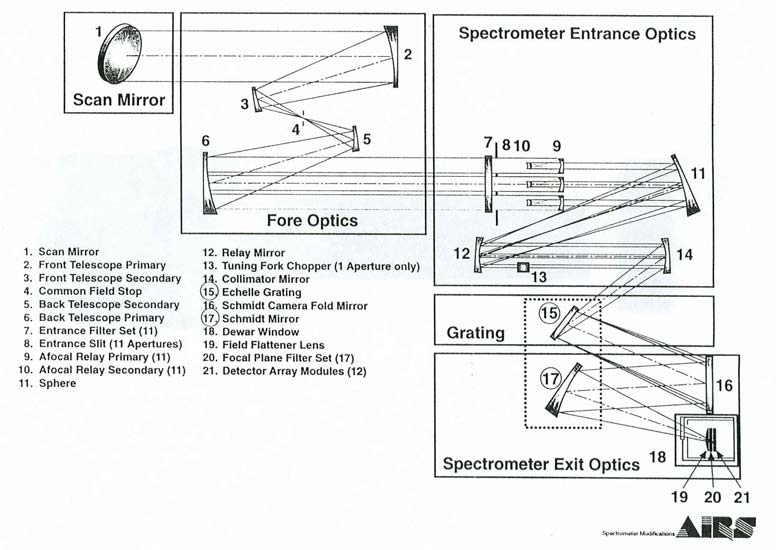
The AIRS optical system has two main objectives. Firstly, a spectrometer separates the wavelengths of light so that each wavelength is measured separately. AIRS achieves this wavelength separation by using a diffraction grating and optical filters at the apertures and detectors. Secondly, since all the wavelength measurements are used together to make soundings, all the wavelength measurements must sample the same column of atmosphere at the same time. AIRS achieves this identical sampling by some fore optics that do pupil imaging.
The multi-aperture grating spectrometer is an pupil-imaging design providing spectral resolution (λ/∆λ) of about 1200 over nearly contiguous spectral coverage from 3.74-15.4 μm. The design approach uses an echelle grating combined with bandpass filters to create a two-dimensional color map.

Afocal Telescope: Light enters the system via the cross-track scan mirror and proceeds to a 4-mirror off-axis telescope assembly with a common 1.1°-diameter field stop. The common field stop ensures high spatial registration for all spectral samples.
Aperture Filters and Slits: The collimated energy exiting the telescope is incident on the spectrometer entrance slit plane containing eleven individual apertures arranged in two staggered columns. An order-sorting bandpass filter covers each slit, which forms the first stage of spectral separation. Ultimately, these eleven slits are imaged onto the focal plane, where each slit image contains the energy from one selected grating order.
Afocal Relay, Chopper, and Collimator: The light from the slits is re-collimated appropriately to be dispersed by the diffraction grating. The light from one of the slits is passed through a mechanical chopper.
Diffraction Grating: The energy is then relayed onto the grating surface where high spectral resolution separation occurs.
Schmidt Camera: The dispersed light is re-imaged onto the focal plane by a Schmidt camera.
Dewar: Light from the camera passes through a window into a dewar containing the focal plane. Cryocoolers keep the focal plane at a cold operating temperature.
Focal Plane Assembly: A second stage of filtering over each FPA array further defines the selected color band, rejects overlapping orders, and serves to reduce background photon levels.
Optical Coatings
The AIRS Spectrometer is a nearly all-reflective instrument with only filters, field flattener, dewar window and detector substrates as refractive components. This approach provides an extremely broad spectrally corrected instrument that avoids the difficulties of broad band multiple element anti-reflection coatings. All reflective surfaces (except the front scan mirror which is protected silver) are gold coated for broad band high IR reflectivity.
Afocal Telescope
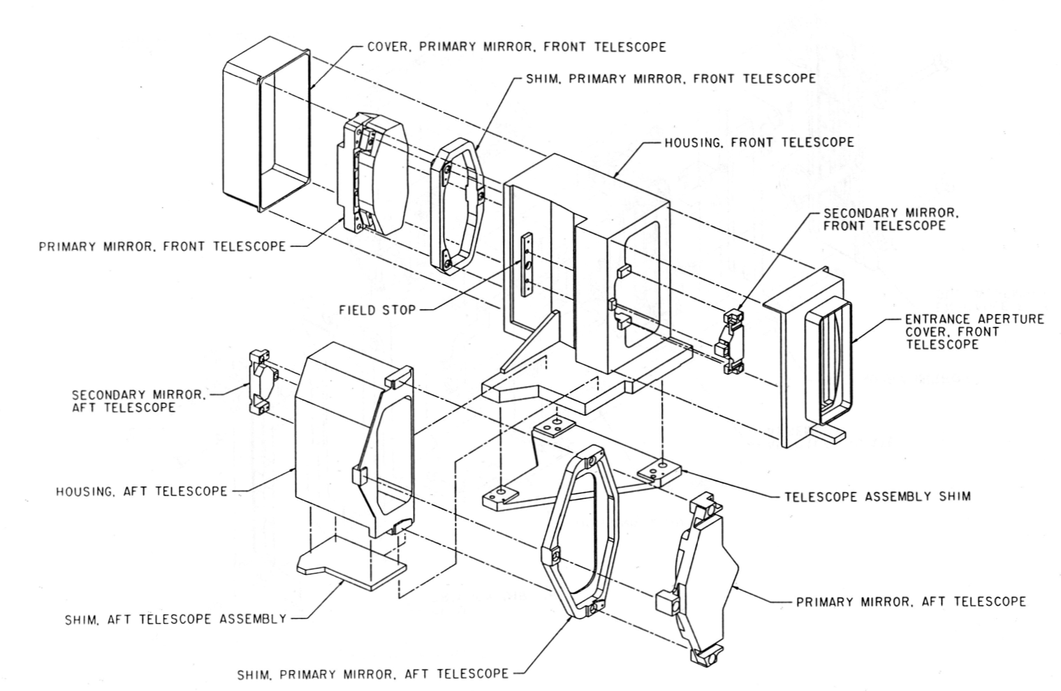
The AIRS fore optics, consists of two identical back-to-back telescopes with an aperture stop in between to provide pupil imaging. The first telescope images the ground onto a field stop. The second telescope images the pupil of the first telescope onto the spectrometer entrance slits. The pupil imaging design was selected to achieve good coregistration, which means that each wavelength is observing exactly the same column of atmosphere.
Even with a pupil imaging design, coregistration can be degraded by
- Aberrations on the fore optics – different parts of the pupil plane ‘see’ a differently aberrated field stop
- Diffraction – wavelengths are diffracted differently at the field stop
- Incidence angles - reflection, refraction, and diffraction efficiency at each surface is a function of the incidence angle of the light, which depends on the slit position in the pupil plane.
- Polarization – differences is polarization due to the view angles on the grating of the individual afocal relays

Fore Optics
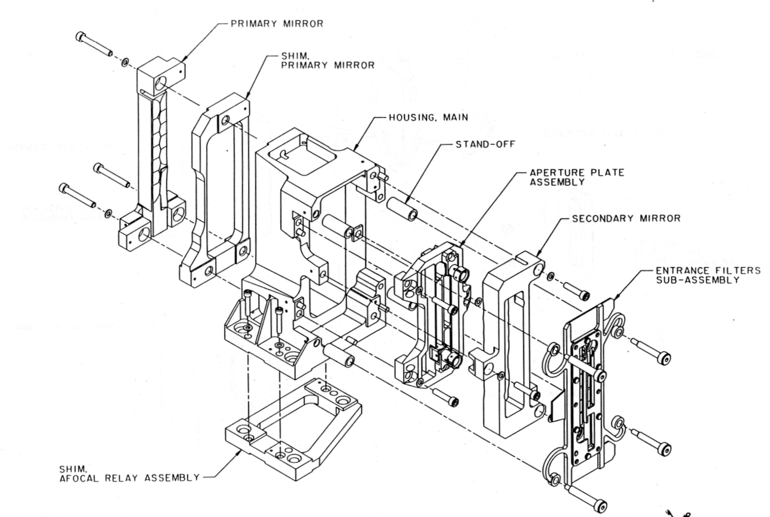
The front end of the AIRS optical system consists of a pair of identical off-axis Cassegrain telescopes. These telescopes function as an imaging and recollimating optical set. The first telescope forms an image at the field stop which defines a common field of view. The telescope is unobscured to avoid diffraction effects that would impact the coregistration requirement. A Cassegrain configuration (as opposed to an off-axis parabola) reduces aberrations (for coregistration) across the aperture plate where the spectrometer entrance slits are located. Each mirror’s size and shape are chosen so that all 11 slits are unobstructed.
The focal length of both Cassegrain telescopes is 156.52 mm.
Field Stop
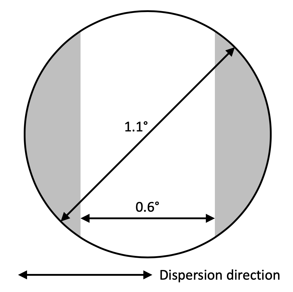
The field stop has a 3-mm outer diameter chosen to make the IFOV be 1.1°. This is 1/3 of the AMSU-A’s 3.3° IFOV. In order to improve spectral variability across the IFOV, the field stop was narrowed to 0.6° wide in the scan direction. The resulting shape is a round disk with flat sides. The actual footprint on the ground is the convolution of the field stop (rotated by the scan mirror), optical aberrations, diffraction, and the scan motion.
Second Telescope
After the light passes through the field stop, AIRS has another Cassegrain telescope, identical to the previous one. This recollimating Cassegrain telescope serves two purposes: re-expanding and collimating the incoming radiation. Also, the telescope relays the entrance pupil (in proximity to the scanning mirror) to the entrance pupil stop (aperture plate), where the entrance slits of the spectrometer are located.
Pupil Imaging
The driving requirement of the AIRS design is that every observed wavelength in the spectrum is sampling the same column of atmosphere. This is called coregistration. The AIRS design uses a pupil imaging spectrometer to achieve this.
In an optical system, a pupil is an intermediate place in the optical train where the light beams from all the points in the image overlap very closely. The aperture stop of the system meets this criterion, and all the other pupils are ‘images’ of the aperture stop. Since the light from all the image points overlap at a pupil, a sample taken from any place in the pupil samples all of the image equally.
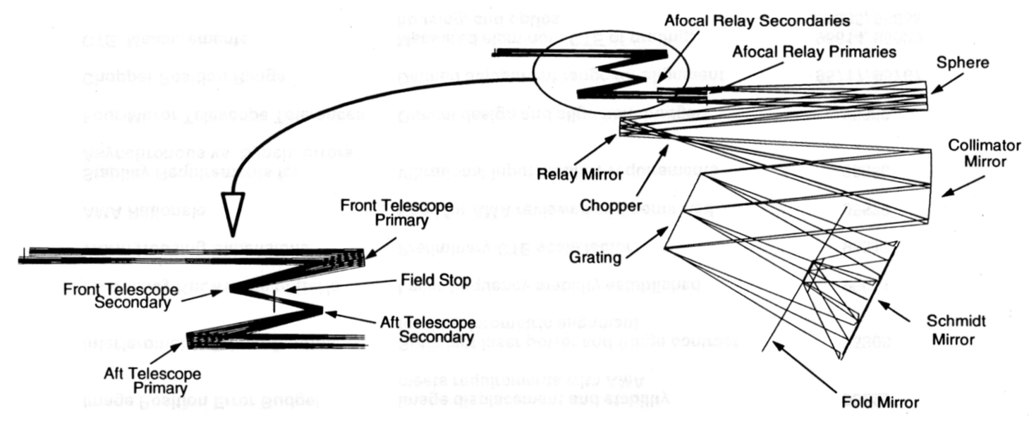
The image below is a schematic of how the images of the pupils and images of the Earth’s surface are transformed by the optics. This version was early in the project, and many of the focal lengths changed. Nonetheless, the diagram shows how pupil imaging works. The horizontal parallel lines from the scan mirror at the top left represent the light from the Earth. Where those lines cross is where an image of the Earth takes place. The other set of horizontal lines represent the images of the pupil. The slits for the spectrometer are placed at a pupil focus.
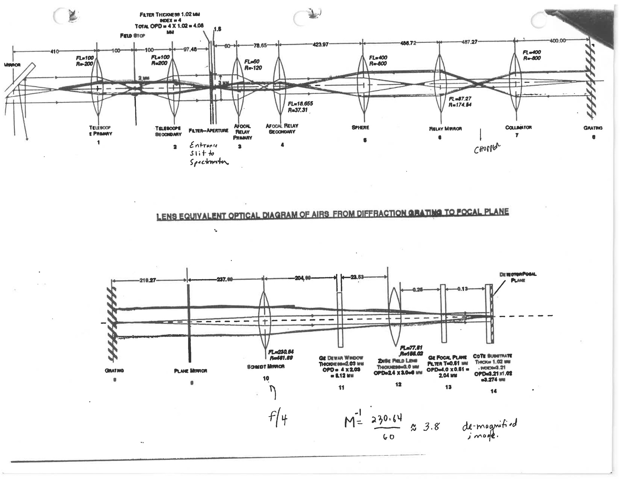
In AIRS, multiple slits are placed at a pupil, so each of these slits sample the same air column. This pupil is inside the Afocal Telescope Assembly. The light from all the slits is dispersed together by a single grating spectrometer.
Filters and Slits
The AIRS aperture surface contains the entrance slits to the spectrometer. Each of the 11 slits has a dedicated filter placed directly in front of the slit. The aperture surface also has two circular holes for alignment, blocked before launch. The aperture plate is followed by 13 (11+2) two-mirror afocal relays.
Filters
Prior to the radiation being incident on the aperture plate, the spectral separation filters are in the beam. Filters at each of the 11 apertures (as well as filters on the focal plane modules) ensure that the light exposing each IR detector is only from the desired grating order.
The filter substrates are Germanium.


Aperture Plate
The aperture plate defines the entrance pupil of the system for each spectral band. Additionally, the multiple-entrance aperture functions as the entrance slits of the AIRS spectrometer and are eventually imaged onto the detector arrays.

The Cassegrain fore optics image the scan mirror onto the aperture plate. Therefore, the total area of the aperture plate’s “apertures” is a major contributor to the required size of the scan mirror. Close packing of the apertures controls the size of the fore optics and scan mirror.
Since everywhere in the pupil plane sees the same column of air, the slits in AIRS can be spaced out to allow each slit to have a custom filter. In a classical slit spectrometer, each position along the slit corresponds to different spots on the ground. For AIRS, the slit length only controls how much area of a detector is illuminated. In AIRS, the PV detectors all have one slit length, while the single PC detector slit length is longer.
Afocal Relay, Chopper, and Collimator
The AIRS optical system has a series of optics that take the light from the aperture slits to the diffraction grating. These optics do three tasks:
- move the apparent position of the slits at the focal plane to better align with the detector module locations
- make room for a chopper to cut the beam to the long wavelength PC detectors
- collimate (make parallel) the light to the diffraction grating.
Afocal Array and Relay

Following the aperture plate is an array of 13 two-mirror ‘afocal’ relays. Eleven of these are for spectrometer channels and two for alignment. These relays reformat the apparent position of the aperture plate slits such that they appear to be in the desired location to be compatible with the focal plane array. These relays magnify by 3.22:1.

The word ‘afocal’ is used here because of how these relays treat the image of the field stop. At the slit, the field stop appears to be very far away, essentially at infinite distance. After these relays, the field stop still appears to be infinitely far away, so it never came to a focus anywhere.
Additionally, it is necessary to effectively displace the long wave PC detector aperture sufficiently to introduce a signal chopper. The ‘afocal’ sphere/relay optics form an intermediate image of all the apertures, providing a location to chop the PC detector aperture light. The second two-mirror relay magnifies by 4.58:1.

Chopper
Light passing through the entrance slits is re-imaged to a location where a tuning fork (“resonant”) chopper modulates the beam. A “chopper” cuts off the light from the source at a fixed frequency. The detectors have 1/f noise (flicker noise), which means that the zero-point drifts with time. The PV detectors mitigate this by having the readout electronics read a zero value between each measurement and then subtracting off the zero read. Since the PC readout electronics cannot switch to read zero, AIRS instead uses a mechanical chopper to modulate the signal. The chopper-closed and chopper-open read values are subtracted to remove the zero-point drift. The chopper runs at a frequency of 357 Hz.

Collimator
The collimator serves the multi-purpose function of:
- Collimating the light from each aperture image (slit) onto the grating.
- Imaging the system field stop onto the grating.
- Placing the apertures at a conjugate such that when they are imaged by the predetermined focal length Schmidt mirror, they have the desired magnification at the detector FPA.

Diffraction Grating
AIRS separates infrared light into wavelengths by using filters and a diffraction grating, which is a set of closely spaced mirror facets cut into a surface. A common example (circa 2000) of a diffraction grating is the surface of a DVD. White light reflecting off of a DVD looks much like a rainbow when viewed at the appropriate angle. The AIRS facets are three thousandths of an inch wide, or about the width of a human hair. See How a Diffraction Grating Works for lots of details.


The grating is at the image of the field stop. In this location all entrance slits (rectangular holes cut in the aperture plate) use the same aperture at the grating.

The grating serves the dual purpose being the disperser and the Schmidt correction element. The Schmidt correction must be face-on to the axis of the Schmidt camera, and thus the shared ruled grating surface as well. The center of each outgoing grating order is then perpendicular to the grating surface.
The AIRS grating was made by Diffraction Products Inc. The grating was made by depositing a thick layer of gold onto a substrate, and then a ruling engine was used to drag a diamond across the surface row by row, cutting the grooves into the soft gold coating. Computer controlled interferometric metrology allowed the ruling engine to also make the surface aspheric.
How a Diffraction Grating Works
The AIRS spectrometer uses the AIRS diffraction grating to separate the wavelengths of light so each may be measured independently. A diffraction grating (in general) is a series of parallel, long, thin mirrors, all with the same width. The mirrors collectively act to produce interference such that when collimated light strikes the mirror a single wavelength is reflected at a given angle, and a spectrum is produced across all reflected angles. When the energy is focused onto a detector array, each detector will see a different wavelength of light.
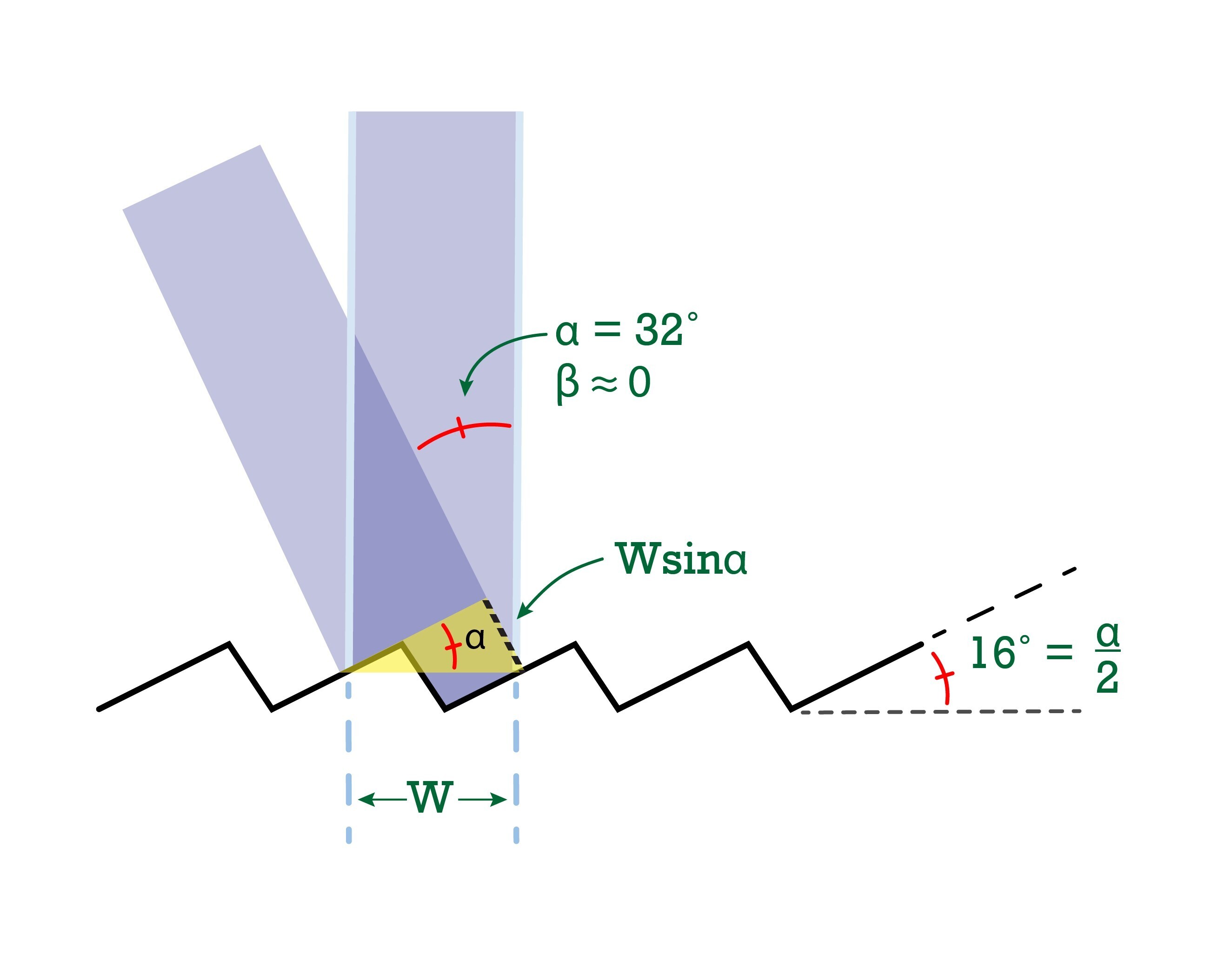
A drawing of the light reflecting off of two adjacent mirror facets would look like the figure below. The input and output angles of the light compared to the surface normal (a vector perpendicular to the surface) are historically called α and β. In order to make the drawing simple, the angle β is shown as zero. This is the angle for the center of the AIRS focal plane assembly, and so is a good first approximation.
In the case of AIRS, W = 77.560 microns, or about 13 mirror facets per mm. Also, in AIRS the incoming light from the slits is all at approximately α = 32° (actually 31.672° or 32.378° depending on which input slit). As seen below, the angles are important to the performance, while the value of W is less so.
Mathematical Details
The light ‘constructively interferes,’ or adds up in a positive way, when the path lengths of the two paths are equal. The path difference for the α side is the distance between facets, W, times the sine of α. The same would be true for the β side. The mathematical formula would then be
{integer number of wavelengths} = {input path length difference} + {output path length difference}
Or equivalently,
mλ = W sin α + W sin β
This is what is called the “grating equation.” Note that if m is zero, then α = -β, which is just a mirror.
AIRS Wavelength Dispersion
Consider the center of each order, where β = 0. The wavelength at the center is
mλC = W sin α
The dispersion is a measure of the amount the slight is spread out across the detector pixels. Dispersion is often given as the number of resolution elements per wavelength. Since α is fixed and β ≈ 0 (so sin(β) ≈ β),
mδλC = Wδβ
Dividing the central wavelength by the resolution element gives
λC / (δλC) = sin α / δβ
The focal length of the Schmidt camera is about f = 225 mm. Focal length is, by definition, the ratio a distance at the detector divided by the corresponding angle at the camera input. AIRS pixels are spaced at p = 0.1 mm, so
λC / (δλC) = f sin α / p
Putting in the values for f, p, and α gives a dispersion of 1200.
Note that the dispersion does not depend on m or W. Since AIRS uses filters to separate out the orders for each detector module, having the wavelengths from each order far apart is beneficial (easier to separate). This means using low numbers for the grating order m. Gratings that work well in more than one order are called echelle gratings.
Schmidt Camera
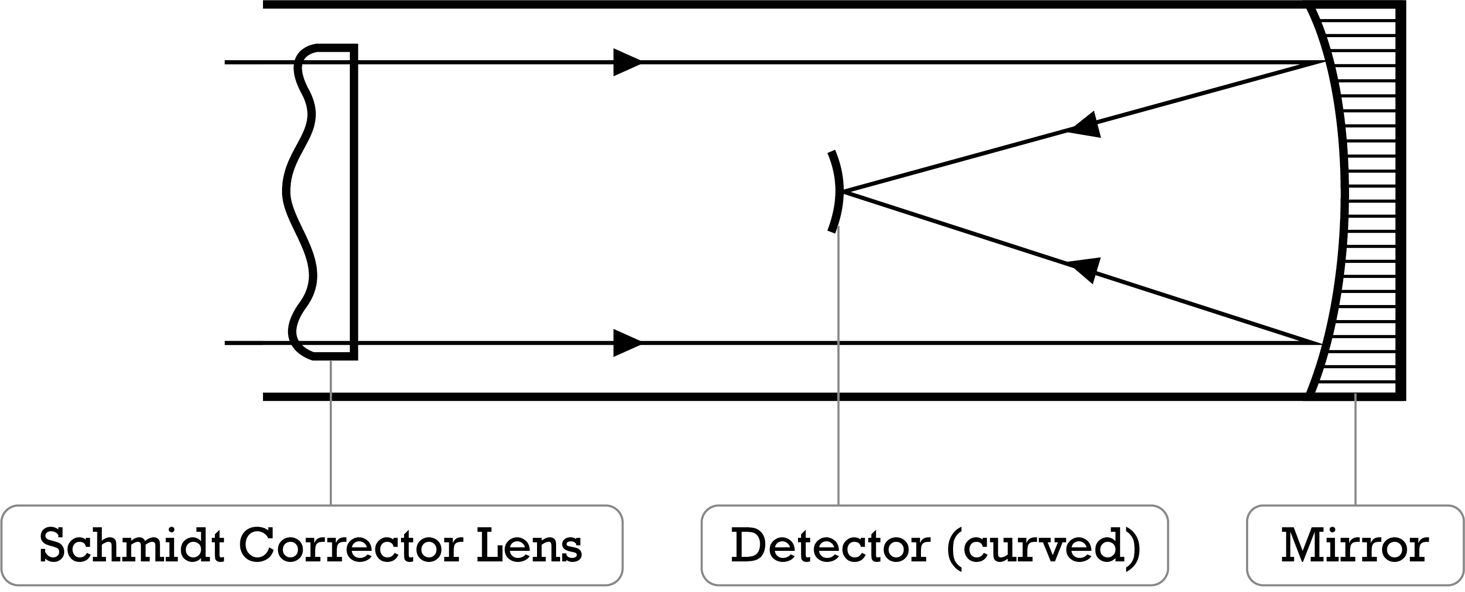
The AIRS camera collects the light from the diffraction grating and focusses it onto the Focal Plane Assembly (FPA). The design is similar to a Schmidt camera, type of camera that has a very wide field of view. The wide field of view is required because the light being dispersed by the grating emerges at various large angles. The Schmidt design works by having a spherical primary mirror, and then correcting the aberrations from the spherical mirror with a corrector plate placed at the center of curvature of the mirror.
AIRS makes the following changes from the classical Schmidt camera design:
- The grating is at the usual location of the corrector plate, so the grating, rather than being flat, is slightly distorted into an aspheric surface such that it does double duty as a corrector plate.
- Since the light from the collimator is approaching the grating at an angle of 32°, the ‘aperture’ of the camera is stretched in one direction, and is thus elliptically shaped. The f-ratio of the camera is then f/1.7 in the stretched dispersion direction and f/2.0 in the cross-track direction.
- Since a Schmidt camera has a spherical focal surface but the FPA is flat, a field flattener lens is incorporated within the FPA to make the light come to a focus at a flat plane.
- The entrance pupil (aka grating) is ‘eccentric’, or moved sideways off axis, so that the FPA does not block the incoming light.
- A fold mirror is added between the grating and the primary mirror for packaging.
Fold Mirror
The Schmidt fold is a flat fold mirror placed in the system for packaging consideration and to facilitate access to the final image by the detector/dewar. Most of the spectrometer optics are in a single plane, usually called an “optical bench.” As both the Schmidt mirror assembly and dewar assembly are too large to fit in the same space, the fold mirror tilts the rest of the optical system so that the Schmidt mirror assembly is above the optical bench and the dewar assembly is below.


Schmidt Mirror
The Schmidt camera mirror is a lightweighted spherical mirror.


Adjustable Mirror Assembly
The adjustable Mirror Assembly (AMA) is the mount for the Schmidt mirror. The AMA can tip, tilt, and focus the Schmidt mirror. Since the alignment performed on the ground before launch is still valid, the AMA has never been needed or used.

Field Flattener
Since the Schmidt configuration has a curved image plane, the system has a field flattener. This optic is close to the detectors and is a lens made from Zinc Selenide. The field flattener is anti-reflection coated to reduce stray light and maintain good transmission through the optical system.

Focal Plane Assembly
The AIRS Focal Plane Assembly (FPA) contains the
The FPA is inside a dewar and is cooled by cryocoolers, because infrared detectors become noisy when warm. The FPA has 12 detector modules containing 17 linear arrays distributed in a two-dimensional pattern on the focal plane. Each linear array has a dedicated filter.

Detectors
The IR detectors are high-sensitivity Mercury-Cadmium-Telluride (HgCdTe). The detectors are of two types: photovoltaic (PV) and photoconductive (PC). In a PV detector, an incoming photon knocks loose an electron. These electrons migrate to one side of the detector, creating a voltage across the detector that can be measured. In a PC detector, the free electrons (and the holes left behind where the electrons were) change the conductivity of the detector material. The current across the detector material is measured.


PV detectors have easier and more compact packaging. These were preferred by the AIRS Project due to lower cost and in simplified engineering. However, since long-wavelength PV detectors with sufficient sensitivity were not available, two of the twelve detector modules (13.7-15.4 μm wavelengths) are PC detectors. The PC detectors have since turned out to be extraordinarily stable, reliable, and relatively immune to radiation effects. On the downside, PC detectors cannot be multiplexed or electrically chopped, so the PC detectors have many more readout circuits and a mechanical chopper.
The PV modules consist of 1, 2 or 4 arrays of back-side-illuminated HgCdTe detectors. These arrays are bi-linear, meaning that the pixels are in a long column with two pixels in each row. The PV detector substrates are CdTe, which is anti-reflection coated on the backside. The PC detector substrates are HgCdTe.
Each module has a unique set of requirements and constraints in terms of wavelength coverage, signal and background flux, and sensitivity. Technologically, the most stressing were the long wavelength modules, particularly M-10 (‘M’ for module) which covers the band from 12.7-13.7 μm. This is mainly because the required sensitivity (signal-to-noise). The longer wavelengths could not meet the sensitivity requirements with PV material and so M-11 and M-12 use PC. The project undertook considerable development in the area of LWIR detector material growth. The detector development work was performed at Lockheed Martin Infrared Imaging Systems (LMIRIS) in Lexington Mass.
Each detector row is 50 μm in the spectral direction. This is approximately 2 detector pixels across the image of the spectrometer entrance slits.

ROIC & Interconnect
Each PV channel has two detector pixels, called ‘A’ and ‘B’. The channel count is 4208/2 = 2104 PV A and B pairs along with 274 PC detectors, makes for 2378 total channels. AIRS can read out any linear combination of the A and B channels. In practice, only A, B, or (A+B)/2 is used.
Each detector module is connected to a low power, 1.2-μm CMOS read-out integrated circuit (ROIC) using indium bumps. The ROIC provides the first stage of signal integration and multiplexing. The 10 PV modules contain a total of 4208 detectors multiplexed down to 26 outputs. The project undertook considerable development in the area of radiation tolerant ROIC design and fabrication, and detector/ROIC interconnect.
Focal Plane Circuit Board
A common ceramic printed circuit board (PCB) mounts the set of 12 modules. The PCB contains power, command and control, and signal interconnects to all PV modules as well as individual lead-outs for the PC detectors. The AIRS FPA hybrid PV/PC approach required special care in the routing, shielding and grounding. This is due to very low noise (nV) PC signals in the presence of high level (V) PV signals. A total of 526 leads interconnect to the PCB assembly using a series of 10 high-density, thin-film flex cables specifically designed for cryogenic operation. Modules were individually assembled, tested and positioned onto the PCB using computer-controlled stages to maintain the requisite optical alignment tolerances of ±15 μm.

Filters
Overlaying the focal plane module is an IR bandpass filter assembly containing 17 individual filters used for grating order selection as well as background suppression. The filter set registers precisely to the focal plane using a dark mirror coated frame for stray light control. A ‘dark mirror coating’ is an optical coating which absorbs as much light as possible and reflects the remainder, so that no light is transmitted.

The assembly also includes a cold shield and a field flattener lens, which is part of the Schmidt exit optics.
Filter/Slit/Order/Filter/Module Mapping
The AIRS spectrometer optics has
- 11 entrance aperture filters
- 11 entrance aperture slits
- 13 afocal relays
- 7 grating orders
- 17 focal plane filters, and
- 12 detector modules.
Making Sense of These Numbers
After the 11 filters and slits, there are 13 afocal relays. Two of these afocal relays exist only for alignment. The circular apertures in the aperture plate that illuminate these two extra afocal relays were blocked after assembly and test.
The dispersion grating is an echelle, meaning that any given angle of light reflecting off of the grating will have a small number of fixed wavelengths. For AIRS, some detector modules detect multiple orders (M-1, M-2, and M-4), while some orders are detected by multiple modules (orders 3, 4, 6, and 10). On top of that, the M-4 module has two filters each for each of the two orders. So, 12 modules, plus 3 extra filters for modules for extra orders, plus 2 extra filters for M-4, comes to a total of 17 filters.
Focal Plane Configuration