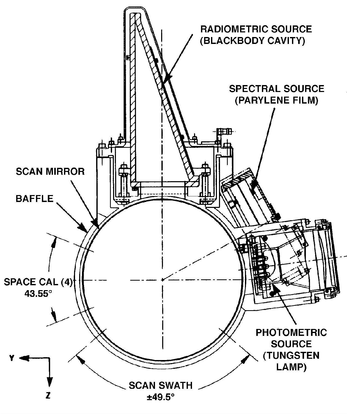
AIRS is a cross-track scanning instrument. A scan mirror rotates around an axis along the line of flight and directs infrared energy from the Earth into the instrument. As the spacecraft moves along, this mirror sweeps the ground creating a scan 'swath' that extends roughly 800 km on either side of the ground track. Between Earth scans, the scan mirror also allows the instrument to view various calibration sources.
The AIRS Scan Head Assembly consists of
- scan mirror
- Scan baffle
- Motor Encoder Assembly
- scan mirror temperature sensors
- scan head housing
- sunshields
- Vis/NIR Sensor Assembly
- On-Board Calibrators.

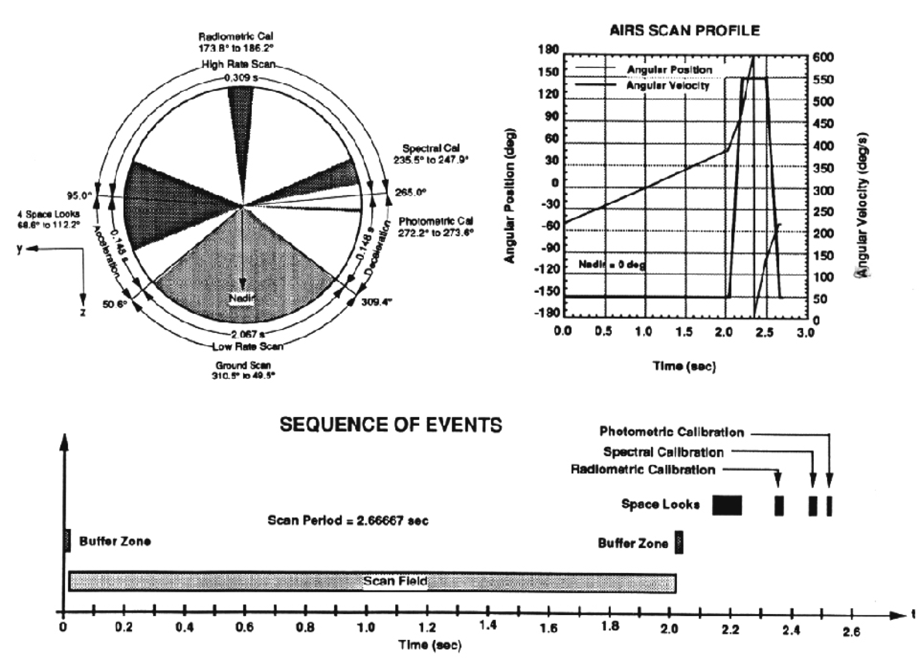
The scan mirror provides ±49.5° (from nadir) Earth coverage along with views to space and to on-board spectral and radiometric calibration sources every scan cycle. Thes scan cycle repeats every 2.667 seconds. See Footprints and Earth Scan for more information.
Scan Mirror
The scan mirror is coated with protected silver. The silver is better than gold because reflectivity is required in the visible for the Vis/NIR photometers, while silver has better has better reflectivity in the infrared than aluminum. A protective over-coating mitigates against the silver being oxidized by atomic oxygen. The scan mirror coating was produced by Denton Vacuum.
The mirror orientation varies with scan angle, changing the orientation of the polarization. Since the spectrometer grating is also polarization sensitive, this produces a scan angle dependent modulation as a function of scan mirror angle.

Scan Baffle
The scan baffle is a rotating baffle surrounding the scan mirror to protect from contamination and stray light.
Scan Mirror Motor
The Motor Encoder Assembly (MEA) consists of a two phase 24-pole brushless DC torquer motor with redundant windings. Motion Systems Corporation developed the MEA. The MEA contains an optical encoder with redundant read heads and motor commutation using a master code disk. The bearings are an angular contact duplex pair mounted back-to-back.

The motor is controlled by a digital servo in the ADM. The servo provides a programmable 2-speed, 2.667-second rotary scan cycle with less than 0.8 milliradian error over the 2-second Earth scan segment.
Calibrators
The AIRS scan mirror views several on-board calibration sources. In addition to the space view, the IR channels view the On-Board Calibrator (OBC) blackbody, a spectral reference source (Parylene) and the Vis/NIR channels view a photometric calibrator. Using space views and the OBC, software (running on the ground) calibrates the IR radiances of a typical scene to an absolute accuracy of 0.2 K (for a scene radiance from a 265 K blackbody).
Space View
AIRS acquires four individual views of space each scan. These space views provide a baseline radiometric reference, compensating for drift of the detector signals. Compared to the Earth, most directions in space (other than an occasional view of the Moon) are dark. Dark, in the infrared, is the same as ‘cold.’
The four space views per scan are at angles 91.6943° (SV1), 101.0621° (SV2), 75.0212° (SV3), and 82.9796° (SV4).
On-Board Calibrator Blackbody
The OBC blackbody provides a warm calibration reference for the infrared channels. It consists of a beryllium housing and cavity, with the inside painted with Aeroglaze Z302. The design is a wedge shape with a cavity depth/aperture ratio of 2:1. The OBC blackbody position is diametrically opposite to nadir (180° scan angle).

The OBC blackbody is temperature controlled to a set point temperature of 308.3 K to within ±0.05 K. The OBC blackbody has four temperature sensors, two used for close-loop thermal control and two that report temperature data. Thermal analysis has shown that temperature gradients in the first bounce surface are less than 40 mK. The OBC blackbody was radiometrically calibrated to an external reference prior to flight.
More details, including measurements of the paint used in the OBC and the thermal analysis of the OBC, can be found in this document:
Ancillary data for AIRS OBC Blackbody
Parylene Spectral Reference
Calibration of the wavelength of each channel uses well-understood atmospheric spectral lines, but functional checkout was done with help from an on-board spectral source. This AIRS spectral reference source consists of a mirror coated with Parylene C, a thin film polymer, that has a unique spectral signature. The Parylene-coated mirror retroreflects the optical image so that the instrument views itself, a cold target, modified by the spectrum of the Parylene. The resulting spectral features are broad compared to the atmospheric absorption lines, making this calibrator primarily useful during pre-flight testing.

Photometric Calibrator Lamps
The Vis/NIR photometric calibrator consists of three selectable lamps and an all-reflective collimator. The optical system includes a lamp monitor photo-diode for lamp stability control. A diffuser plate achieves source uniformity.


Earth Scan
The AIRS scan mirror rotates 360° every 8/3 of a second (2.667 seconds), so that AIRS does three scans for every 8-second AMSU-A scan. The scan mirror motor has two speeds:
- During the first 2 seconds, the mirror rotates slowly, generating a scan line with 90 footprints of the Earth scene.
- During the remaining 0.667 seconds, the scan mirror completes one complete revolution rapidly and views various calibrators.
Timing details:
- Chopper runs at 357 Hz
- Cryocooler runs at (357 Hz)/8 = 44.625 Hz
- Commensurate frequency prevents cryocooler noise and vibration from interfering w/ readout
- 8 PC detector ground samples per footprint
- ½ of each chopper cycle is dark, so 16 reads, alternating dark and light
- 8/(357 Hz) = 22.409 ms per footprint
- Mechanical scan rate is 49.114°/s
- Scan rate is programmable and this value was measured on orbit
- (49.114°/s) * (22.409 ms) = 1.101° footprint spacing
- This is chosen to approximately 1/3 of AMSU-A’s 3.333° spacing.
- Total scan width is (1.101°/footprint * 90 footprints) = 99.05° = ±49.53°
References
Lambrigtsen, B.H. and Lee, S.Y., 2003. Coalignment and synchronization of the AIRS instrument suite. IEEE Transactions on Geoscience and Remote Sensing, 41(2), pp.343-351. Link
Lambrigtsen, B.H., 2003. Calibration of the AIRS microwave instruments. IEEE Transactions on Geoscience and Remote Sensing, 41(2), pp.369-378.