The AIRS electronics design emphasizes radiation tolerance and redundancy to increase lifetime. The system is microprocessor-controlled and has a high degree of configuration flexibility via ground commands.
The electronics are complex by virtue of the high detector count and the redundancy. AIRS uses over 30,000 electronic components. High-density component and packaging techniques minimize size, mass and power. These components and techniques include SMT components, custom hybrids, and great reliance on FPGA technology.
-
Example AIRS custom hybrid
-
Example AIRS custom hybrid
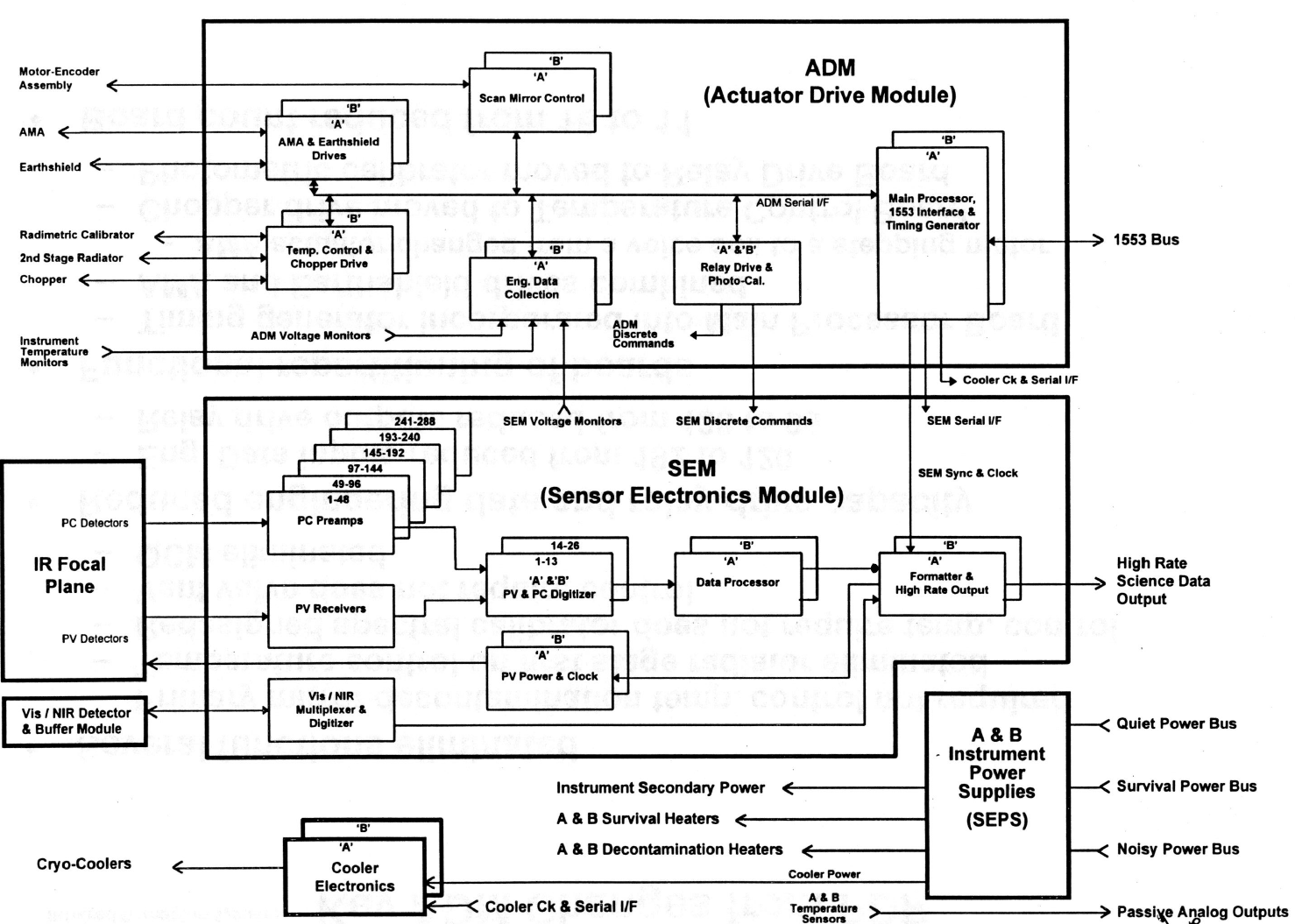
The majority of the AIRS electronics split into four separate modules:
- Actuator Drive Module (ADM) – control, processing, and timing
- Sensor Electronics Module (SEM) – science signal processing
- Sensor Electronics Power Supply (SEPS) – power conditioning
- Cryo Cooler Electronics (CCE) – operate the focal plane cooling system.


Sensor Electronics Power Supply
The AIRS Sensor Electronics Power Supply (SEPS) provides Instrument power conditioning. The SEPS takes unregulated 28 Vdc inputs from the Aqua spacecraft to produce 15 isolated, regulated outputs for system operation. Two identical power modules within the SEPS assembly provide redundancy.
Sensor Electronics Module
The AIRS Sensor Electronics Module (SEM) provides the entire on-board science signal processing chain, taking data from the focal plane assembly (FPA), performing all on-board data manipulation, and outputting the science data to the Aqua spacecraft. Critical low noise PC signal processing functions take place on-board but off the focal plane, in parallel with high-level PV signal processing operations.
The electronics provide DC restore, whereby drift from the detectors is offset to keep the signals within the dynamic range of the Analog to Digital Converter. The electronics also provide on-board radiation circumvention by acquiring multiple frames of data per footprint and removing radiation spikes that occur before averaging the frames.
The SEM does the following:
- Provides power and clock to the PV detectors
- Receives the PV signals
- receive 26 high-level PV outputs
- multiplex PV signals
- Pre-amplifies the PC detector signals
- 274 low-level PC signals
- Each PC signal is hardwired to an individual hybrid low-noise preamplifier, band limited
- Digitizes the PV and PC signals
- digitized at 12-bit resolution (Analog Devices AD9871)
- Processes the data
- pipeline data processing operating at 6 Msamples/s.
- Multiplexes and digitizes the Vis/NIR signals
- Formats the combined data for output to the spacecraft
- combines the PV/PC data, Vis/NIR sensor data, and engineering data and outputs the result to the Aqua spacecraft


PC Pre-Amp Board


PV Receiver Board


PV & PC Digitizer Board


Data Processor Board


Formatter and Output Board


PV Power and Clock Board


Vis/NIR Processor Board


Actuator Drive Module
The AIRS Actuator Drive Module (ADM) performs command and control, redundancy management, engineering data collection, and motor control functions. The ADM does the following:
- Controls the Adjustable Mirror Assembly (AMA)
- Controls deployment of the Earth shield
- Controls the Radiometric Calibrator temperature
- Controls the 2nd Stage Radiator with a trim heater
- Controls the Chopper (provides the Chopper drive)
- Controls the Scan Mirror Motor Control Assembly (MCA) using a digital servo
- Collects the Engineering Data (voltages and temperatures)
- Controls relays
- Controls the Photometer Calibrator
- Provides instrument timing
- Provides the main processing using an embedded processor (Harris RTX2010)
- Communicates to the spacecraft through a MIL-STD-1553 bus.
Software provides the command and control functions with program code primarily written in C and operated out of RAM. Instrument redundancy management to the circuit card level is via ground command of a series of 96 relays, with drivers packaged in hybrid form to minimize circuit area.


Processor and Timing Board


Engineering Data Collection Board


Relay Driver Board


Temperature Control and Chopper Board


Adjustable Mirror Assembly and Earth Shield Board


Scan Mirror Drive Board


Cryocooler Control Electronics

Two separate Cooler Control Electronics modules (CCEs), one CCE for each cooler assembly, provide cooler power conditioning and control. The CCEs provide high efficiency, synchronized drive to the compressor pistons. Software feedback loops control the cold head temperature and compressor vibration output based on three sensors. These sensors are a cold head temperature sensor, a capacitive piston position sensor, and an accelerometer mounted on the compressor. The CCE controls cold head temperature to ±0.01 K and compressor vibration output to less than 0.5 Newton. A serial bus interface to the AIRS controller (ADM Main Processor) provides communication to either cryocooler.