Instrument Calibration and Characterization Ancillary Files
Spatial Response Function Ancillary Data
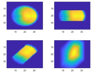
Each of the AIRS 2378 spectral channels views a nominally 13.5 km footprint as projected onto the ground. From the Aqua orbit altitude of 705 km, the projected beam is nominally 1.1 degree as measured from the satellite. The beam shape, or Spatial Response Function (SpatialRF) is irregular and depends on the cross-track scan angle (consisting of 90 footprints) and varies from channel to channel. Most channels have about the same SpatialRF, however due to the nature of the AIRS design, the SpatialRF’s can change substantially for channels near the end of the 17 individual detector modules. SpatialRF’s represent the response of the individual channel to the underlying scene radiance. The signal from the AIRS is proportional to the product of the underlying radiance distribution of the scene and the SpatialRF.
Measurements
Spatial response characterization was primarily conducted at the level of the IR Sensor Assembly rather than the complete instrument. Nevertheless, sufficient testing on the fully assembled instrument confirmed the accuracy of earlier data. Initial data collection involved detailed 2D raster map scans to assess instrument response, whereas later tests only required vertical and horizontal cross-axis spatial scans through the AIRS IFOV center. These cross-axis scans were compared to similar tests from the IR Sensor Assembly, showing a high degree of similarity in response contours for spectral samples near the center of the shortest wavelength array. Data from both the detailed 2D raster map scans and the cross-axis scans were used to construct a set of tophat functions for all channels. These tophat functions were then combined with a model of the field aperture, inserted post measurement, and the effect of scan motion (rotation and integration) of the scan mirror. The Figure below shows an example of the SpatialRF for the B side of channel 620.

SpatialRFs and Data
SpatialRFs are available in three files in NetCDF format, AIRS_Spatial_Response_Functions_A.nc, AIRS_Spatial_Response_Functions_B.nc, and AIRS_Spatial_Response_Functions_AB.nc, corresponding to the A, B and AB gain settings of the instrument detectors respectively. These files can be downloaded from the AIRS Documentation Page. Spatial Response Functions are normalized to 1 for the center footprint, (20,20) in the 39 x 39 array. Each file contains the following variables:
| Name | Size | Bytes | Class | Comments |
|---|---|---|---|---|
| AIRS_SpatialRF | 39x39x 2378x90 |
1302097680 | Single | Spatial Response Function for each of AIRS 90 footprints |
| x_spatial | 39x39 | 12168 | Double | Scan direction angle projected towards Earth relative to the center of AIRS in degrees |
| y_spatial | 39x39 | 12168 | Double | Track direction angle projected towards Earth relative to the center of AIRS in degrees |
| wnum | 2378x1 | 9512 | Single | Frequency (cm^-1) |
References
I. Yanovsky, T. S. Pagano, E. M. Manning, S. E. Broberg, B. M. Sutin, Quantifying Uncertainties in Atmospheric Infrared Sounder (AIRS) Spatial Response Functions. SPIE Optics and Photonics, Earth Observing Systems XXIX, 2024.


