Instrument Calibration and Characterization Ancillary Files
Polarization Ancillary Data
The AIRS instrument uses a grating to provide spectral calibration and dielectric filters to reject out-of-band energy. These optical devices tend to introduce polarization as light passes through them or is reflected (in the case of the grating). The AIRS scan mirror that is used to map the Earth also introduces polarization. If the Earth scene is unpolarized (generally assumed to be true for the atmosphere) then the impact of the polarization of the AIRS only comes into the radiometric calibration, since the orientation of the scan mirror is different for the space views than it is for the Earth views. The effect manifests as an offset that modulates with amplitude proportional to the radiant emission of the scan mirror times the product of the polarization factor of the scan mirror, pr, and the rest of the optical train, pt, and the phase of the scan mirror relative to the spectrometer. This is discussed in more detail in the following reference:
Thomas S. Pagano, Evan M. Manning, Steven E. Broberg, Hartmut Aumann, Robert C. Wilson, Ken Overoye, "Updates to the radiometric calibration of the Atmospheric Infrared Sounder (AIRS)," Proc. SPIE 12685, Earth Observing Systems XXVIII, 126850K (4 October 2023); https://doi.org/10.1117/12.2676416
Measurements
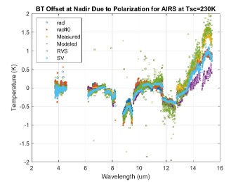
The polarization product, prpt, was determined pre-flight and on-orbit several ways, as shown in the Figure below.
Key:
rad: Determined from the intercept of the radiometric response curves acquired pre-flight at nadir
rad40: Same as ‘rad’ but at a scan angle of 40 degrees
Measured: Polarization factor of the optical train as measured using wire grid polarizers x polarization factor as-measured of the scan mirror.
Modeled: Polarization product as modeled using component data of the filters, scan mirror and a model of the grating polarization
RVS: Polarization product determined from test where the AIRS was rotated while viewing a stable blackbody
SV: Polarization product determined using the 4 space views for the entire mission evaluated at launch.

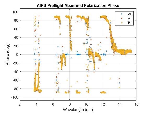
Polarization phase was less certain at the time of launch and set to zero in the Version 5 L1B. This may have introduced radiometric errors vs scan angle. We have corrected this in Version 8. Our best estimate of the polarization product and phase is obtained from the AIRS space views, SV. It changes with time to account for changes observed in the scan mirror, and is dependent on the A, B and AB detector configuration. These values represent the AIRS Project’s best estimate for science quality data. Validation of the AIRS polarization product and phase used in Version 8 was performed with the Aqua Deep Space Maneuver (DSM). Discussion and results of the DSM test can be found in section 2.5.2 of the the AIRS V8 L1B Test Report:
Pagano, T. et al., “AIRS Version 8 Level 1B Test Report”, May 22, 2024, https://disc.gsfc.nasa.gov/information/documents?title=AIRS%20Documentation
Polarization Coefficients and Data
The polarization product and phase for Version 8 can be found in every granule of the L1B data product. The variable names are ‘prpt’, and ‘polar_ang’ and represent our best estimate of these products at the time of the granule and used in the AIRS radiometric calibration.
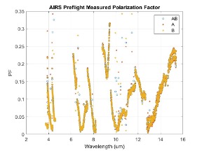
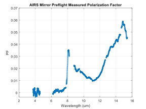
The AIRS optical train polarization amplitude, PH, and phase, δ, and mirror polarization, pt, were measured pre-flight. They may be useful for some applications. More information on the pre-flight measurements and comparisons to model can be found at
AIRS instrument polarization response: Measurement methodology. Gigioli Jr., George W.; Pagano, Thomas S. Proc. SPIE 3759 (1999). https://doi.org/10.1117/12.372676
A NetCDF file with the pre-flight polarization measurement information identified in the table below can be downloaded from the AIRS Documentation Page. The file name is AIRS_V8_L1B_Polarization_Ancillary.nc. The Polarization Factor (PF) is measured with the scan mirror oriented at nadir. The orientation of the phase, δ, is with 0 degrees aligned along track. There are three PFs and phase terms corresponding the AB, A and B states of detectors respectively, however, the AB state is an average of the A and B states as it was not measured during this test. The order of the data are in AIRS PGE ID, i.e. same as the Level 1B data product.
| Name | Size | Bytes | Class | Comment |
|---|---|---|---|---|
| PF_meas | 2378x3 | 57072 | double | AIRS Polarization Factor (unitless) |
| ph_meas | 2378x3 | 57072 | Double | AIRS Polarization Factor (degrees) |
| p_r_meas | 2378x1 | 19024 | double | AIRS Mirror Polarization Factor (unitless) |
| side_name | 3x2 | 12 | char | Test Side (AB, A or B) |
| wnum | 2378x1 | 19024 | double | Frequency (cm^-1) |
| rs_meas | 2378x1 | 19024 | double | S component of Mirror Reflectance |
| rp_meas | 2378x1 | 19024 | double | P component of Mirror Reflectance |


