AIRS Project Instrument Suite
The AIRS Project Instrument Suite has a total of five cross-track scan mirrors to scan the Earth’s surface:
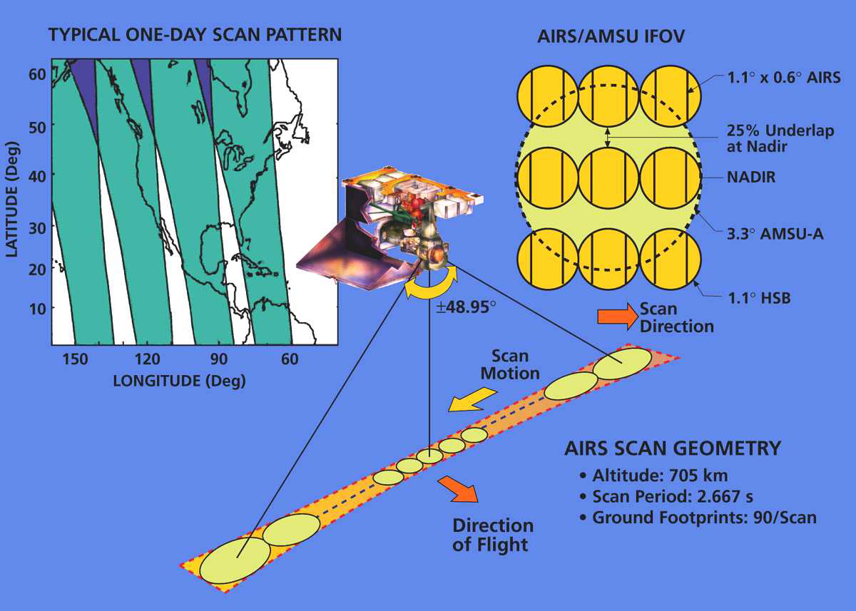
In order to combine the data from these instrument scans together, the scan patterns are aligned with each other. AMSU-A and HSB (based on AMSU-B) are both heritage instruments that already had commensurate footprints, with 3×3 AMSU-B footprints for every AMSU-A footprint. AIRS has the same 3×3 footprints for each AMSU-A footprint as HSB.
Footprint Spacing
AMSU-A’s footprints are spaced every 3.333°, while the AIRS footprint spacing is every 1.101°. Although not exactly commensurate, the footprint alignment is within the original requirements across a 90-footprint AIRS scan.
Footprint Size and Shape
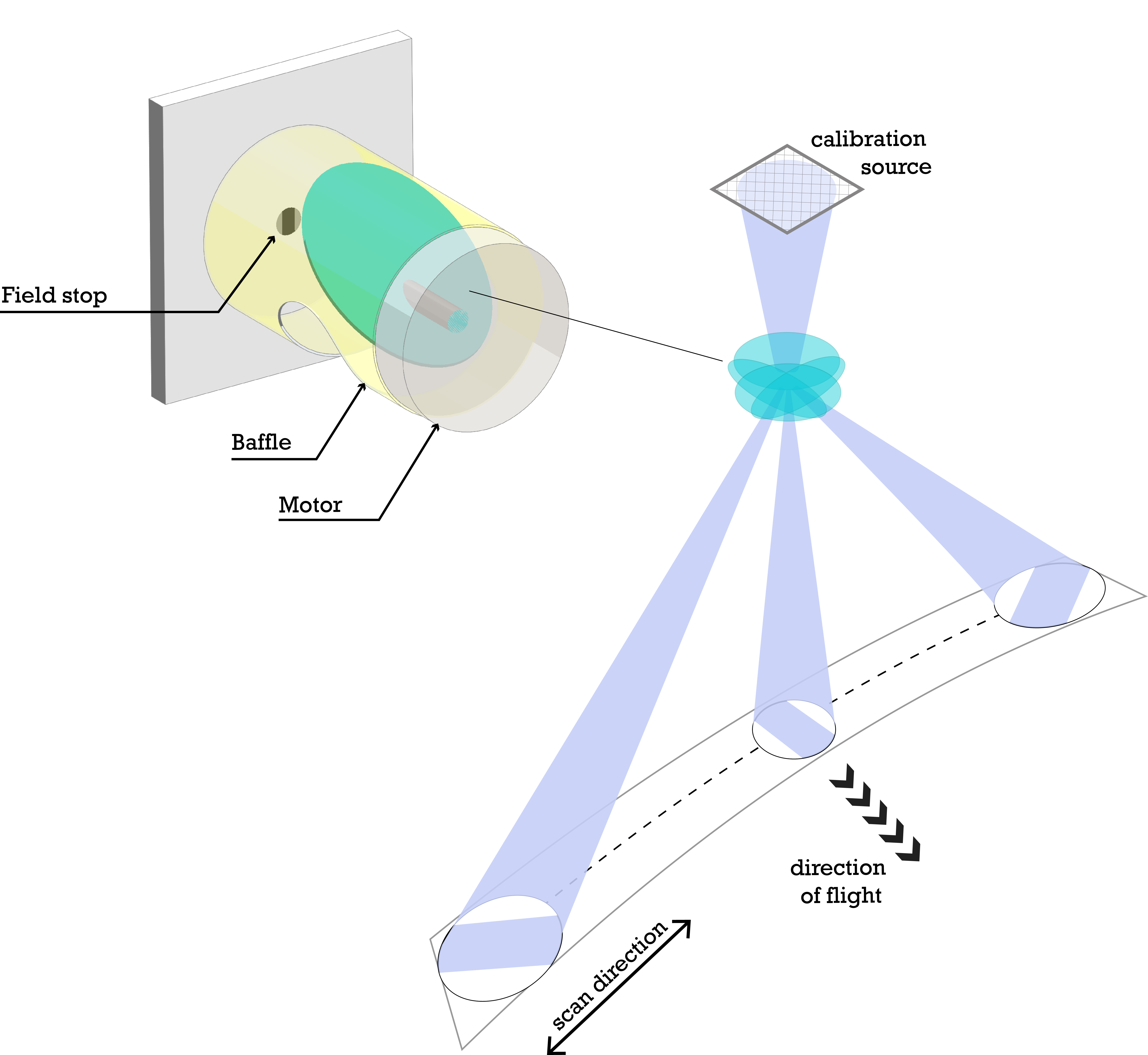
- The beam shape envelope 1.1° disk. The response over angle was measured before flight for every detector pixel.
- Next, the beam is cut down to 0.6° in dispersion direction by the field stop (scan direction at nadir). The field stop was added to reduce spectral variability across the beam.
- The beam is then rotated depending on scan mirror position.
- The beam is smeared out along the scan direction by 1.101°, due to the spacecraft motion.


Calculation at Nadir
For Aqua’s nominal altitude of 705.3 km, the diameter of the column at the ground at nadir is 13.54 km, with flat sides 7.39 km wide. The 1.101° scan motion makes the footprint envelope shape into a 13.54 km × 20.94 km rectangle with slightly soft corners. When the Full Width Half Maximum (FWHM) is considered instead of the envelope, then the footprint is approximately a 13.5-km square.
Vis/NIR Photometer
Each of the four channels has eight pixels cross track. Each pixel has an instantaneous field-of-view (IFOV) of 0.190° across-track and 0.149° along-track, with a 0.037° gap between adjacent pixels along-track. A deliberate defocusing of the optics effectively fills in the gap between detectors, allowing complete ground coverage.
| Spatial Resolution | 2.3 × 1.8 km (across-track, along-track) |
| Spatial Sampling | 8 × 9 pixels per AIRS 13.5-km footprint |
Cross-Track Scan Reflectors

All the instruments in the AIRS Project Instrument Suite perform cross-track scanning. A mirror mounted on a rotating shaft parallel to the direction of motion causes the instrument to sample a line of angles perpendicular to the direction of motion.
The reflectors are mounted on a scan axis at a 45° tilt angle, so that radiation reflects perpendicular to the scan axis (a 90° turn angle). As the spacecraft moves along, this mirror sweeps the ground creating a scan 'swath' that extends roughly 800 km on either side of the ground track.
Image Rotation
One interesting effect of the scan mirror is that the image as seen by the instrument is rotated as the mirror scans. So, if the instrument spectrometer slit were parallel to the track direction (along track) at nadir, then it would be perpendicular to the track motion when the scan mirror is at 90° to the side. This effect is linear, meaning that the image rotation is 45° when the scan mirror is at 45° from nadir.
Coregistration and Clouds
AIRS has a requirement for coregistration, which means that each wavelength is observing exactly the same column of atmosphere. Imperfections in the instrument lead to degraded coregistration. This is due to many effects within the instrument, such as that the light received on different detectors is reflected from surfaces at different angles (and so different reflectivities), or vignetting, where part of the light is blocked. Many of these effects are mitigated in the L1C data product.
If the coregistration is perfect, then any two wavelengths sample the air column down to the Earth’s surface exactly the same. In this ideal case, if half of the beam is blocked by clouds, then both wavelengths are equally blocked, and so the two wavelengths could be safely compared. However, when coregistration is not perfect, a partially cloudy air column will have one wavelength sampling a slightly different column of air, with one channel seeing less of the cloud and perhaps deeper into the atmosphere. The result is that AIRS soundings in partially cloudy scenes are, in general, less accurate. Imperfect coregistration can also be seen in the AIRS spectrum as discontinuities or breaks in the spectrum. In other words, coregistration make a difference then the scene being observed is inhomogeneous.
The “Figure of Coregistration” (abbreviated as “Cij”) is a number between 0 and 1 that indicates how well two wavelengths sample the same air column. If the Cij = 0, then the two wavelengths are samples of air columns that do not overlap at all, while Cij = 1 means that the two air columns are identical. The actual instrument Cij from a ground measurement is shown below (where ‘i’ is the wavelength 4.1836-microns on detector module M-1), with the colors chosen so that red is 1.0 and blue is 0.9 (still very good!).

Rather than using the full Cij for evaluating coregistration, the centroids alone are often sufficient for evaluating coregistration. Cij was mostly used during AIRS assembly and testing, while the centroids are now used for AIRS project calibration.

References
Denis A. Elliott, Thomas S. Pagano, and H. H. Aumann. "The impact of the AIRS spatial response on channel-to-channel and multi-instrument data analyses", Proc. SPIE 6296, Earth Observing Systems XI, 62960I (8 September 2006). doi:10.1117/12.679542
T.S. Pagano, H. Aumann, D. Elliott, E. Manning, “Improving AIRS radiance spectra in high contrast scenes using MODIS”, Proc. SPIE 9607-19, San Diego, CA (2015)